Being an engineer, I love to combine the precision and function driven aspect of engineering based solution sets with the “form as function” aspect of art. I realized one day that I could use simple hobby electronic circuit design to create a rather unique T3 Logo project.
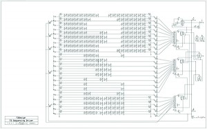
I started with the concept of the logo done in 3mm orange LEDs. After creating the layout I worked up a design for a Sequencing circuit using simple 4017 Decade Counters and some logic chips. The T3 LED logo had 22 rows and the circuit had 25, so I decided to make the rows blink in order from top to bottom and then flash all the LED twice with a pause between, then it starts over. I won’t bore you with all the details, but I had to restructure the board layout several times as new problems surfaced when I changed the plan, or in some cases failed to plan. The most significant revision resulted from not thinking through the power requirements. I had originally used a ground plane to connect ALL the LEDs to ground through a resistor. Long story short, each row has different numbers of LEDs and this would have resulted in each row being a different brightness. So, now each row has it’s own grounding resistor and there are isolating diodes so I can switch ALL the LED’s on (the battery will only last a minute if I do) and I added an external power supply (see battery problem just mentioned.)
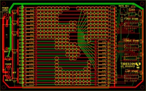
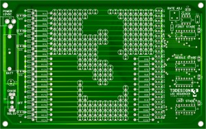
I ordered a Printed Circuit Board (PCB) and then my 4th son and I spent a good part of Friday night and some time Saturday morning populating the PCB and it works!